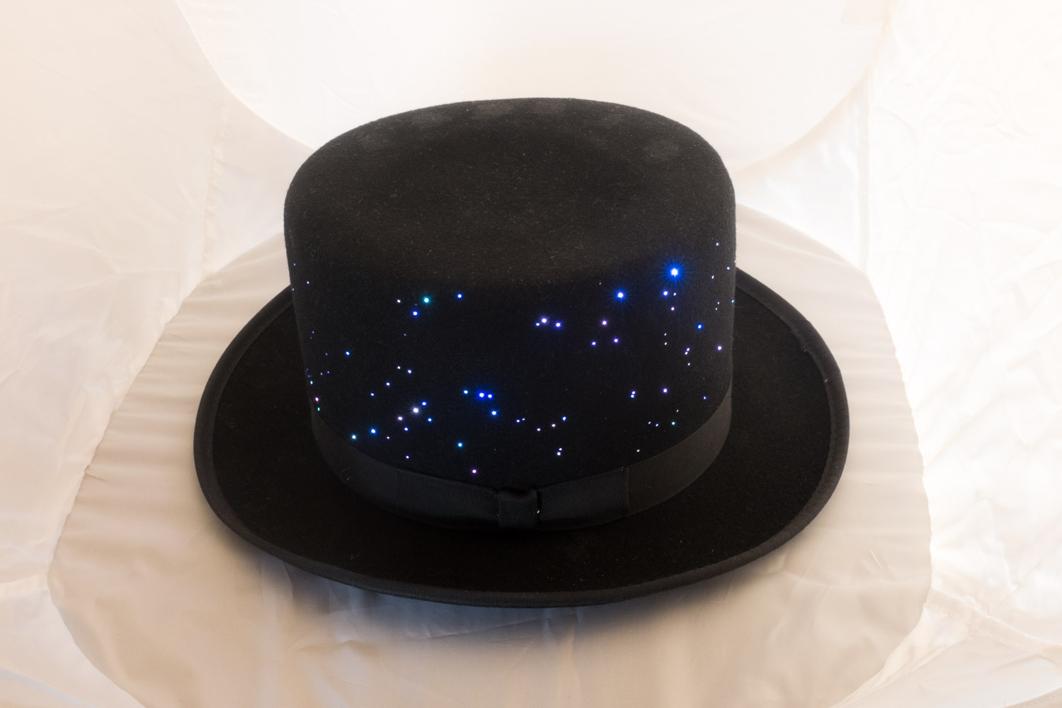
My Hat! It’s Full of Stars

Three or more years ago an instructable by Chris Knight reached my attention. (I have shamelessly stolen the title of his instructable for the title of this post because it is just. Too. Good. But all credit to Chris with apologies to Mr. Kubrick).
ANYWAY. I saw that instructable and knew immediately that I wanted to build my own starfield hat. Fast-forward 3 years. A friend is having a birthday party. The theme of the party is “Sparkle”. Anything sparkly will do. I finally had my excuse. With a couple of months warning to build it and most of the materials I needed already on hand I set to work.
Getting Started
The basic premise is a top hat that’s been stuffed with a couple hundred short pieces of optical fiber (like that color-changing wand toy you had as a kid) that are hooked up to color-controllable LED units which are in turn hooked up to a microcontroller (arduino or similar).

All this gets attached to the crown of the hat and then the fibers are threaded through the sides, glued in place, and then clipped flush to the felt. My first task would be getting the lights working.
After considerably fiddling I ended up with a driver library for the LED modules I used. This let me send an RGB value to a particular light and have it hold that value. But I didn’t want flickering lights. I wanted fading. I wanted fading at different speeds to different colors all at the same time. So that necessitated another library to manage colors over time. I ended up with an approach that let me define a set of parameters for each light and then would update iteratively.

The end result was a program that gave each light a “target value” and some speed parameters. On every frame the light changes its current color closer one step closer to its target value, and when it reaches its target it randomizes all its parameters (target color, step size, and speed). I limited the color randomization to whites, blues, and purples to keep a bit of a night sky theme. The finished code for the hat itself is available here if you’re interested.
Build Prep
Once the software was at a proof-of-concept point I started putting together the hardware. Figuring out how to attach everything to everything else was a bit of an adventure. I took an old IDE ribbon cable and cut it into short segments with 6 wires each, tinned the wires, and replaced the headers on the LED modules with the ribbons.

Once that was put together I needed a flat, diffused surface to attach the ends of the optical fibers to. The LED packages on the ShiftBrite boards I used were square with hemispherical domes on top, so I sawed off the domes and sanded the newly flat surfaces to diffuse them.
I knew I wanted a density of about 2.5 stars per square inch and my hat had approximately 74 square inches of surface area that I’d be lighting, which put the number of fibers needed at around 180. With 180 fibers and 6 LEDs that meant I needed to attach about 30 fibers to each LED.

To attach the fibers to the LEDs I first taped bundles of fibers together, then cut them to length with a hot utility knife. Some heat-shrink tube slipped over the LED package and around the taped-up end of the fiber bundle held things in place – put some glue (E6000 works well, or hot-melt glue can be okay, but you need to be careful with both the glue gun and the hot air gun to avoid melting your fibers) inside the heat-shrink tube and shrink it. To finish it off I wrapped a zip-tie around each bundle to really squeeze things down.
Starfield Pattern (or: How I was Nerd Sniped by my Brother In Law)
Chris Knight threaded his fibers randomly, but I wanted something that had a closer relationship of some kind with the real night sky – some patch of sky or another, perhaps. Maybe each point representing a galaxy in the Hubble deep field, or drawing out constellations.
The trick was that whatever I picked needed to be fairly evenly distributed across the entire field and needed to have the right number of points (around 180).

So what to pick? Naked-eye visible stars in some patch of sky? Galaxies in the Hubble Deep Field? Known quasars? I asked my brother-in-law – who is something of an astronomy buff – if he had any suggestions for images that might suit my needs. He didn’t, but he did point out that most astronomy data is freely available and that there’s a python library that will process the common data formats for astronomy data and help produce charts and the like.
I became enamored with data presented using the Galactic Coordinate System and set off to find some sort of dataset with points that I could map across the whole sky and then place on my hat. (As it turns out, the aspect ratio of my hat is such that I can show the full 180° around the sky for 30° above and 30° below the galactic plane).
Unfortunately most things we can see fall into one of two categories:
- far away and we can only see them in dark areas of the sky
- in our own galaxy
The corollary to #1 is that we usually can’t see through our galaxy to see them, so most data is either dense along the major axis of my plot and sparse away from it or the other way around. There’s very little that is actually distributed uniformly across the sky.
Little, but not none. The mighty Gamma Ray Burst is such an unbelievably energetic event that we can detect them clear across the universe, and the bright soup of light that is the Milky Way doesn’t really get in the way at all. So I plotted the last 2 years of GRB detections that were seen within 30° above and below the galactic disk, mirrored the plot, and then printed it out onto a long strip of paper. That paper I wrapped around the crown of my at and taped in place to use as a guide.

Finishing Up
Gluing all the electronics into the hat was a bit of a challenge. I initially tried using contact cement, but that was a terrible failure – it didn’t glue anything to the hat very well and it soaked into and through the felt, leaving visible splotches on the outside of the hat. Much better was E6000 glue available from craft stores such as Michaels or Jo-Ann Fabrics
To thread the fibers through the hat, I poked a large upholstery needle through one of the points on my guide plot from the outside of the hat then followed it carefully back out through the hole it made with a fiber from one of the bundles. I actually partitioned my data so that the first 30 or so detections were plotted as red dots, the next 30 as blue dots… which kept me from having to randomize which bundle I took each fiber from. I worked in three layers, pulling all of the fiber for the top third of the hat first, then the next third, and finally the last third. After each batch I glued all the newly pulled fibers in place against the inside of the hat with some E6000 (a toothpick was an imperfect but serviceable applicator for this purpose).

After threading the fibers the hat was quite fuzzy with loose fibers bouncing and swishing around. I left it alone for a day at this point for all the glue to set, then came back through and tugged on each fiber to make sure they were all glued. To clean it up I just used some flush-trim wire cutters to snip each fiber down all the way to the surface of the felt.
I knew I wanted to be able to turn the hat on and off without digging around inside it, and I also wanted to be able to select different blink patterns for the lights. My first attempt at this was to put a momentary pushbutton switch under the bow in the band, but debouncing that was a pain and the button was fairly low-quality so it was actually quite difficult to register a press.
I scrapped that idea and added a cheap tilt switch instead. Some tape let me fiddle with the angle and with a little tinkering I had a hat that looked perfectly normal until I tipped it at an onlooker at which point it’d light up!
(I added the tilt switch and refined the mode-switching after recording that video – I ended up with the tilt-switch toggling the lights on and off, and each time they came back on they were running the next pattern. I ended up limiting my patterns to “nebula”, “colorwheel”, and “sparkle”)
More Details
Interested in the specific materials and components I used? Read on!
The Lights
I picked the lights that I used based on what I had on hand, but actually, when I make another I’m going to use the same modules. I had a dozen “ShiftBrite” pixels that I got years ago and never used. These turned out to be pretty remarkable little boards, although perhaps a more conventional LED package would be better for laying things out inside the hat.

I wanted to prototype my software on the Particle Core. Unfortunately all the sample code and libraries I could find for working with the ShiftBrites was written for arduino, and was close enough to the metal that the AVR-specific code wouldn’t work for the ARM-32 chip that is the…erm core, as it were, of the Core.
The “shift” part of the name comes from the fact that the modules combine shift registers (Serial-In, Parallel-Out – meaning you can send data over time from relatively few pins on your microcontroller and then throw a switch that dumps all those bits out in parallel!) with PWM controllers. You send data down the chain into the shift registers, then latch them out into the PWM controllers’ registers and those controllers take care of managing 10-bit PWM on each of three channels (red, green, and blue). You can also fine-tune the current for each channel if you care about matching colors between chips exactly, but I didn’t need that level of detail.
Shift registers are convenient because their Data/Latch/Enable/Clock interface works out to be a degenerate case of the SPI protocol, which means that you can use your microcontroller’s dedicated SPI hardware to send data to them. Once I got that working I bundled it up into a ShiftBrite driver library that works on both arduino and Particle platforms!
Also, 10-bit color resolution per channel is actually remarkably high – most boards will only give you 8 bits – so these are excellent choices for applications that need gentle fading between colors, or decent color matching. As an aside, if you are interested in making LEDs fade aboslutely gorgeously check out the following:
- Gamma Correction: PWM brightness is a linear beast, but the human eye has a logarithmic response to intensity. Gamma correction is a way to adjust your PWM so linear changes to your brightness values actually look linear to your eye.
- FadeCandy: Micah Scott’s amazing device to help build stunning, large-scale lighting installations.
- Aurora: A lovely flower of LEDs with some fancy color fading work done to change colors in lovely ways. Also check out their blog for other things that they’ve made.
If you want to play with ShiftBrites yourself, they’re retired from a lot of places, but at the time of this writing still seem to be available from the manufacturer
Documentation is also available from the manufacturer, but if that ever goes down I’ve got the datasheet for the A6281 driver chip that the ShiftBrite breaks out here.
The Fibers
After talking with Chris I ended up buying a bundle of 300 pieces of optical fiber each 3’ long – I only needed about a foot per star. I ended up going with 0.75mm fiber from eBay, mostly on Chris’ suggestion. When choosing the fiber diameter, things to consider are:
- Flexibility – thinner fiber is more flexible than thicker.
- Number and size of stars – you can pack more thinner fibers onto each light, so thinner fiber will give you more stars than thicker, but thicker fibers will make larger, brighter stars.
- Effort Required – with more start you’ll have more work to do threading the hat.

The fibers are remarkably sturdy and much harder to kink than I expected. Plus, when they do kink they don’t lose too much light at the junction and are still able to produce a bright point on the side of the hat. A heat gun will cause them to become very flexible so if you’re careful you can shape them while warm and they’ll hold that shape once they cool (tight bends will, of course, leak light). I actually used this trick to get a little more room inside the hat after I threaded all the fibers – they took up too much space inside the hat and made the hat sit unnaturally high on my head, so I used the heat gun to relax them down away from my head.
Do be careful with heat though – a heat gun is enough to soften and ruin the fibers very quickly; hot-glue guns and soldering irons are far less forgiving.
The Microcontroller(s)
I wanted to use something fairly low-profile in this project, and I had a Lilypad Arduino left over from a previous project that I thought would work well. The LilyPad is difficult to prototype with, though, because of the sewable pads, so I decided to prototype with (and possibly use) a Particle Core. Eventually I decided not to use the Core because I didn’t need to add my hat to the Internet of Things and I didn’t want to sort out how to prevent the hat from failing when it couldn’t connect to wifi (such as if I took it somewhere new) and the delay involved while it attempts to connect to its cloud.
I scavenged a more traditional Arduino from another project to prototype with and ran into some fascinating bugs when switching between them due to the fact that the core’s ARM chip is a 32-bit architecture while the arduino’s AVR is 8 bits.
When I make an updated version I’ll actually go with an Arduino Pro Mini from SparkFun – the LilyPad is nice for wearables when you need soft circuits, but the sewable pads are a pain in the but when the rest of your circuit is hard. Using the pro mini will keep things small (even smaller, actually!) and make it easy to wire everything up.
Power
I powered my hat off a 2000mAh Lithium Ion battery using Adafruit’s excellent PowerBoost 500 board. This board takes the 3.7v output from the battery and bumps it up to 5.2v (the extra .2v is within the 5v spec and helps avoid brownouts due to voltage drops across long wire runs like you often see in wearables). It has low-voltage cutoff to protect the battery, a low-battery warning indicator, and the ability to disable the output by pulling one of the pins to ground, which lets you add a power switch that doesn’t have to be able to pass the full current of your project.
I thought I could do without the onboard 5v battery charging offered by its big brother, the PowerBoost 500c, but I actually came to regret this. Unplugging the battery from the board is an enormous pain and I’ve pulled several fibers out of the hat attempting to disconnect and reconnect the battery already. When I do it again I’ll use a board with charging ability. I bought one from SparkFun because I was already buying stuff from them anyway, but the PowerBoost 500c is probably as good or better and currently slightly cheaper. The one thing I want to look into is reducing the quiescent current draw as far as possible to avoid draining the battery when it’s powered off. There’s some info in the comments on this tutorial about doing that, so I’ll be looking into that.